Adafruit Motor Shield V1.2: Difference between revisions
Jump to navigation
Jump to search
Created page with "Image:TArduinoL298NDualMotorDriver.png == Summary == The Adafruit Motor Shield V1.2 is an Arduino-compatible shield designed to control up to 4 DC motors. It provides independent speed control for each motor using PWM, with acceleration and deceleration slope settings. == Description == The Adafruit Motor Shield V1.2 uses two motor driver ICs (Driver1 and Driver2), each controlling 2 DC motors. Each motor can be individually enabled, configured with an initial..." |
(No difference)
|
Latest revision as of 11:27, 25 August 2025
Summary
The Adafruit Motor Shield V1.2 is an Arduino-compatible shield designed to control up to 4 DC motors. It provides independent speed control for each motor using PWM, with acceleration and deceleration slope settings.
Description
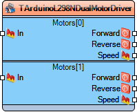
The Adafruit Motor Shield V1.2 uses two motor driver ICs (Driver1 and Driver2), each controlling 2 DC motors. Each motor can be individually enabled, configured with an initial value, and controlled with acceleration (Slope Run) and deceleration (Slope Stop) properties.
It provides analog PWM outputs for motor speeds and digital pins for enable and latch operations.
Diagram:
Categories
- File:TArduinoDigitalCategory.png Category Digital - Motor control components.
- File:TArduinoPWMCategory.png Category PWM - Pulse Width Modulation devices.
Properties
Driver1
Motor1
- Enabled - Enables or disables Motor 0.
- Initial Value - Default speed for Motor 0 (0.5).
- Slope Run - Acceleration slope for smooth speed ramp-up of Motor 0.
- Slope Stop - Deceleration slope for smooth braking of Motor 0.
Motor2
- Enabled - Enables or disables Motor 1.
- Initial Value - Default speed for Motor 1 (0.5).
- Slope Run - Acceleration slope for smooth speed ramp-up of Motor 1.
- Slope Stop - Deceleration slope for smooth braking of Motor 1.
Driver2
Motor1
- Enabled - Enables or disables Motor 2.
- Initial Value - Default speed for Motor 2 (0.5).
- Slope Run - Acceleration slope for smooth speed ramp-up of Motor 2.
- Slope Stop - Deceleration slope for smooth braking of Motor 2.
Motor2
- Enabled - Enables or disables Motor 3.
- Initial Value - Default speed for Motor 3 (0.5).
- Slope Run - Acceleration slope for smooth speed ramp-up of Motor 3.
- Slope Stop - Deceleration slope for smooth braking of Motor 3.
Pins
Input Pins
- Driver1 Motor1 In - Analog input to control Motor1.
- Driver1 Motor2 In - Analog input to control Motor2.
- Driver2 Motor1 In - Analog input to control Motor3.
- Driver2 Motor2 In - Analog input to control Motor4.
Output Pins
- Motor Speed 1 - Analog output speed control for Motor1.
- Motor Speed 2 - Analog output speed control for Motor2.
- Motor Speed 3 - Analog output speed control for Motor3.
- Motor Speed 4 - Analog output speed control for Motor4.
Other Pins
- Enable - Digital enable pin for shield operation.
- Data - Digital data pin for serial communication.
- Clock - Digital clock pin for synchronization.
- Latch - Digital latch pin to update driver states.
