Microchip MCP3424 ADC (I2C): Difference between revisions
Jump to navigation
Jump to search
Created page with "Image:TArduinoMCP3424ADC_I2C.png == Summary == Microchip MCP3424 ADC with I²C interface for quad-channel analog-to-digital conversion applications. == Description == The **MCP3424 ADC** provides quad-channel analog-to-digital conversion with configurable resolution, gain settings, and sampling modes. It features I²C communication interface, programmable gain, and supports both continuous and single-channel sampling for precision multi-channel measurement applicat..." |
(No difference)
|
Latest revision as of 00:06, 9 September 2025
File:TArduinoMCP3424ADC I2C.png
Summary
Microchip MCP3424 ADC with I²C interface for quad-channel analog-to-digital conversion applications.
Description
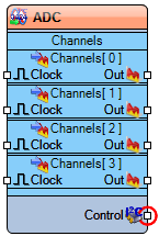
The **MCP3424 ADC** provides quad-channel analog-to-digital conversion with configurable resolution, gain settings, and sampling modes. It features I²C communication interface, programmable gain, and supports both continuous and single-channel sampling for precision multi-channel measurement applications.
Diagram:
Properties
- Enabled – Enables or disables the ADC.
- Address – I²C device address (Default: 568).
- Bits(Resolution) – ADC resolution in bits (Default: 12).
- Name – Component identifier name.
- Gain – Programmable gain setting.
- Channels – Channel configuration (4 configurable channels):
- Item[0] – Channel 0 settings:
- Enabled – Enables channel 0 (Default: True).
- Item[1] – Channel 1 settings:
- Enabled – Enables channel 1 (Default: True).
- Item[2] – Channel 2 settings:
- Enabled – Enables channel 2 (Default: True).
- Item[3] – Channel 3 settings:
- Enabled – Enables channel 3 (Default: True).
- Item[0] – Channel 0 settings:
- Mode – Sampling mode configuration:
- All Channels – All channels sampling mode (Default: True).
- Channel – Single channel selection (Default: 0).
- Continuous Single Channel – Continuous single channel mode (Default: False).
Pins
Input Pins
- Clock – ADC clock input.
Output Pins
- Channels[0]: Out (analog) – Channel 0 conversion output.
- Channels[1]: Out (analog) – Channel 1 conversion output.
- Channels[2]: Out (analog) – Channel 2 conversion output.
- Channels[3]: Out (analog) – Channel 3 conversion output.
- Control (digital) – Control and status signals.
- Interface (i2c) – I²C communication interface.
Categories
- File:TArduinoDigitalCategory.png Category Digital – Digital conversion components.
- File:TArduinoAnalogCategory.png Category Analog – Analog measurement components.
- File:TArduinoI2CCategory.png Category I2C – I²C-enabled devices.
- File:TArduinoADCCategory.png Category ADC – Analog-to-digital converters.
- File:TArduinoMicrochipCategory.png Category Microchip – Microchip semiconductor devices.
