NXP PCA9556 GPIO(I2C): Difference between revisions
Created page with "Image:NPXPCA9556GPIOComponent.png == Summary == The NXP PCA9556 is a 8-bit GPIO expander controlled via the I2C bus. It provides eight bidirectional I/O pins that can be individually configured as inputs or open-drain outputs. == Description == The NXP PCA9556 GPIO (I2C) component interfaces with the PCA9556 chip, adding 8 configurable GPIO channels to your system over an I2C connection. Each channel can be independently set as an input to read a logic level or as..." |
(No difference)
|
Latest revision as of 08:50, 13 November 2025
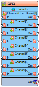
File:NPXPCA9556GPIOComponent.png
Summary
The NXP PCA9556 is a 8-bit GPIO expander controlled via the I2C bus. It provides eight bidirectional I/O pins that can be individually configured as inputs or open-drain outputs.
Description
The NXP PCA9556 GPIO (I2C) component interfaces with the PCA9556 chip, adding 8 configurable GPIO channels to your system over an I2C connection. Each channel can be independently set as an input to read a logic level or as an open-drain output to drive a signal low or into a high-impedance state.
The Auto Config property for each channel, when enabled, automatically applies the initial configuration (direction and value) for that specific channel to the chip upon startup.
Diagram:
Properties
Address – The I2C slave address for the PCA9556 device.
Per-Channel Properties (Channel[0] to Channel[7])
Auto Config – When True, automatically applies the Initial Value and Is Output configuration for this channel to the chip on startup.
Initial Value – The default Boolean value set on the channel when it is configured as an output.
Is Inverted – When True, the logic level of the pin is inverted (High becomes Low, and Low becomes High).
Is Output – Defines the direction of the channel. When True, the channel is an output; when False, it is an input.
Pins
Input Pins
In [0] – Boolean input for Channel 0 (only active when channel is an output).
In [1] – Boolean input for Channel 1 (only active when channel is an output).
In [2] – Boolean input for Channel 2 (only active when channel is an output).
In [3] – Boolean input for Channel 3 (only active when channel is an output).
In [4] – Boolean input for Channel 4 (only active when channel is an output).
In [5] – Boolean input for Channel 5 (only active when channel is an output).
In [6] – Boolean input for Channel 6 (only active when channel is an output).
In [7] – Boolean input for Channel 7 (only active when channel is an output).
Output Pins
I2C – The I2C bus connection. This pin must be connected to the board's I2C pin.
Out [0] – Boolean output from Channel 0 (only active when channel is an input).
Out [1] – Boolean output from Channel 1 (only active when channel is an input).
Out [2] – Boolean output from Channel 2 (only active when channel is an input).
Out [3] – Boolean output from Channel 3 (only active when channel is an input).
Out [4] – Boolean output from Channel 4 (only active when channel is an input).
Out [5] – Boolean output from Channel 5 (only active when channel is an input).
Out [6] – Boolean output from Channel 6 (only active when channel is an input).
Out [7] – Boolean output from Channel 7 (only active when channel is an input).
Categories
- File:TArduinoGPIOCategory.png Category GPIO – General Purpose Input/Output expansion and control.
- File:TArduinoI2CCategory.png Category I2C – I2C communication and device control.
