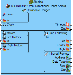
TSCINBUNY Omni Directional Robot Shield
File:TArduinoTSCINBUNYOmniDirectionalRobotShield.png
Summary
The TSCINBUNY Omni Directional Robot Shield is a comprehensive robotics platform featuring omni-directional motor control, ultrasonic ranging, infrared remote, and line tracking capabilities for advanced robotic applications.
Description
This advanced robotics shield supports omni-directional movement through independently controlled front and rear motors on both left and right sides. It integrates ultrasonic distance measurement, infrared remote control reception, servo control, and triple-sensor line tracking. The shield is designed for complex robotic projects requiring precise movement control, obstacle avoidance, and autonomous navigation capabilities.
Diagram:
Properties
- Infrared Remote – IR remote control configuration:
- Clear Interval (mS) – Time interval for clearing IR data in milliseconds (Default: 1000ms).
- Elements – Configurable IR remote elements (Default: 0 items).
- Enabled – Enables/disables IR remote functionality (Default: True).
- Replace NECRepeat Code – Replaces NEC repeat codes (Default: True).
- Motors – Omni-directional motor control configuration:
- Left Motors – Left side motor configuration:
- Enabled – Enables/disables left motors (Default: True).
- Front – Front left motor settings:
- Enabled – Enables/disables front left motor (Default: True).
- Reverse – Reverses motor direction (Default: False).
- Initial Value – Motor starting speed percentage (Default: 0.5).
- Rear – Rear left motor settings:
- Enabled – Enables/disables rear left motor (Default: True).
- Reverse – Reverses motor direction (Default: False).
- Slope Run – Acceleration slope rate (Default: 0).
- Slope Stop – Deceleration slope rate (Default: 0).
- Right Motors – Right side motor configuration:
- Enabled – Enables/disables right motors (Default: True).
- Front – Front right motor settings:
- Enabled – Enables/disables front right motor (Default: True).
- Reverse – Reverses motor direction (Default: False).
- Initial Value – Motor starting speed percentage (Default: 0.5).
- Rear – Rear right motor settings:
- Enabled – Enables/disables rear right motor (Default: True).
- Reverse – Reverses motor direction (Default: False).
- Slope Run – Acceleration slope rate (Default: 0).
- Slope Stop – Deceleration slope rate (Default: 0).
- Left Motors – Left side motor configuration:
- Ultrasonic Ranger – Distance measurement configuration:
- Enabled – Enables/disables ultrasonic sensor (Default: True).
- Pause Time (mS) – Measurement pause time in milliseconds (Default: 100ms).
- Ping Time (uS) – Ultrasonic ping duration in microseconds (Default: 2μs).
- Servo – Servo motor control:
- Enabled – Enables/disables servo (Default: True).
- Initial Value – Servo starting position (0.0-1.0) (Default: 0.5).
- Max Pulse – Maximum pulse width in microseconds (Default: 2400μs).
- Min Pulse – Minimum pulse width in microseconds (Default: 544μs).
- Reversed – Reverses servo direction (Default: False).
- Use PWM Library – Enables alternative PWM library (Default: False).
- Timeout (mS) – Servo timeout in milliseconds (Default: 10000ms).
- Timeout Value Units – Measurement units for timeout value.
- Name – Component identifier (Default: TSCINBUNY Omni Directional Robot Shield).
Pins
Input Pins
- Digital 3 (digital) – IR receiver input.
- Digital 18/AnalogIn[4] (i2c-sda/analog) – Ultrasonic echo input.
- Digital 19/AnalogIn[5] (i2c-scl/analog) – Ultrasonic trigger input.
- Digital 14/AnalogIn[0] (digital/analog) – Left line tracking sensor input.
- Digital 15/AnalogIn[1] (digital/analog) – Center line tracking sensor input.
- Digital 16/AnalogIn[2] (digital/analog) – Right line tracking sensor input.
- Left Motors In (digital/pwm) – Left motors control input.
- Right Motors In (digital/pwm) – Right motors control input.
- Servo In (digital/pwm) – Servo control input.
- Power (power) – Shield power supply input.
Output Pins
- Digital 2 (digital) – Motors clock output.
- Digital 4 (digital) – Motors store output.
- Digital 5 (digital/pwm) – Right motors speed output.
- Digital 6 (digital/pwm) – Left motors speed output.
- Digital 7 (digital) – Motors enable output.
- Digital 8 (digital) – Motors data output.
- Digital 9 (digital/pwm) – Servo output.
- Timeout Out (digital) – System timeout status output.
- Line Following Out (digital) – Line following status output.
- Infrared Remote Out (digital) – IR remote data output.
- Left Motors Out (motor) – Left motors power output.
- Right Motors Out (motor) – Right motors power output.
Categories
- File:Robotics.png – Robotics and automation components.
- File:Shield.png – Arduino shield form factor components.
- File:Motor.png – Motor control components.
- File:Ultrasonic.png – Ultrasonic distance measurement components.
- File:Infrared.png – Infrared communication components.
- File:OmniDirectional.png – Omni-directional movement components.
