Magnetic Compass LIS3MDL(SPI)
Jump to navigation
Jump to search
File:TArduinoLIS3MDLMagneticCompassSPI.png
Summary
LIS3MDL 3-axis magnetic compass with SPI interface for detecting magnetic fields and orientation.
Description
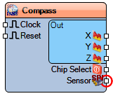
The **LIS3MDL Magnetic Compass (SPI)** measures the X, Y, and Z components of magnetic fields. It supports configurable sample rates, full-scale range, power modes, self-test, and temperature compensation. Performance modes for XY and Z axes can be individually set. The sensor communicates via SPI and can be reset or synchronized using a clock input.
Diagram:
Properties
- Enabled – Enables or disables the compass.
- Fast Rate (boolean) – Enables faster measurement rates.
- Full Scale Range (Gauss) – Measurement range (default 4 Gauss).
- Low Power Mode (boolean) – Reduces power consumption.
- Power Down (boolean) – Puts sensor in power-down mode.
- Sample Rate (Hz) – Frequency of measurements (default 20 Hz).
- Self Test (boolean) – Enables self-test mode.
- Temperature Compensation (boolean) – Compensates for temperature variations.
- XY Performance Mode – Low, Medium, High, UltraHigh.
- Z Performance Mode – Low, Medium, High, UltraHigh.
- SPISpeed – SPI communication speed (default 8000000).
Pins
Input Pins
- Reset (clock) – Resets the sensor.
- Clock – Sampling clock input.
Output Pins
- X (analog) – X-axis magnetic field output.
- Y (analog) – Y-axis magnetic field output.
- Z (analog) – Z-axis magnetic field output.
- Sensor (SPI) – SPI interface for communication and configuration.
Categories
- File:TArduinoDigitalCategory.png Category Digital – Digital sensors and interfaces.
- File:TArduinoSPIcategory.png Category SPI – SPI-enabled devices.
- File:TArduinoSensorCategory.png Category Sensors – Magnetic and orientation sensors.
